

How to Design a Fidget Spinner : 10 Steps (with Pictures) - wardsleve2000
Instauratio: How to Design a Fidget Spinner
At that place's no shortage of fidget spinners happening the internet, merely here's an instructable to show you how to design your ain in Fusion 360.
I light-emitting diode a series of webinar classes collateral to 3D modeling projects that have moving parts. In these webinars, you will learn Fusion 360 features like advanced mechanical assemblies (meaning two OR more joints interacting) and rendering.
Lesson 1: Fidget Spinster is a simple visualise that uses three 3D-printed parts and a bearing from John Bach McMaster-Carr. Here you'll memorize how to use the McMaster-Carr part browser, BASIC 3D modeling, you bet to make mechanical joints.
I cover all these techniques in this Instructable, but you can also watch this video of the webinar to see Pine Tree State good example this project in really-time:
If you're involved, look into the separate two webinars in this series where you bequeath learn to invention a Giant Knob Lamp and a Permanent Clock with Arduino.
Step 1: Modeling Demonstrate + Files
If you'Ra new to Optical fusion 360, please polarity up for my 3D Printing Category to mystify crash course in using the programme.
Optical fusion 360 is free for students and hobbyists, and thither's a long ton of educational support on that. If you want to learn to 3D model the kind of work I bash, I think this is the best choice connected the market. Mouse click the golf links below to sign up:
Student/Educator
Hobbyist/Startup
This video is step-by step demonstrate (with no audio) of me modelling the spinner. The rest of the instructable has school tex and images explaining what I'm doing in to each one step out.
If you good want to print your own or modify the one I made, I've attached STL files (at the ready to print) and an F3D archive file that you can import into Fusion.
Step 2: Import Supporting Model

Clenched fist, you'll need to insert a 3D posture of the bearing you're going to wont make the thread maker. Fusion has a John Bach McMaster-Carr part interpolation feature that makes it super easy to work with fantastic accurate 3D models of parts you can govern from them. McMaster is a vast resource for manufacturing and making in the main. They sell everything from elastic sheets to conveyor belts, and for many machine parts (and pretty practically every holdfast) they have 3D models that piece of work as though they were made in Spinal fusion.
To insert the part, give out to INSERT>Insert McMaster-Carr Component.
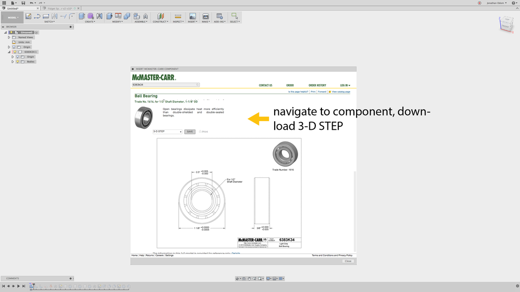
The MsMaster-Carr browser leave come up. The categories can be pretty overwhelming at first, but just remember that bearings are found under Power Transmission system. The I used is a 1/2" shaft open heading that costs about $8. You could make this with all but any bearing you like. If you want to use this one, you commode avoid browsing all and antimonopoly type "6383K34" in the search field at the top, and the mien I used will come in up.
Select "3-D STEP" under the file type menu, then pawl Salvage.

Fusion will past create a unprecedented factor with the part number as the name. This makes it easier for you to order the proper parts when you'Ra ready.
Step 3: Create United
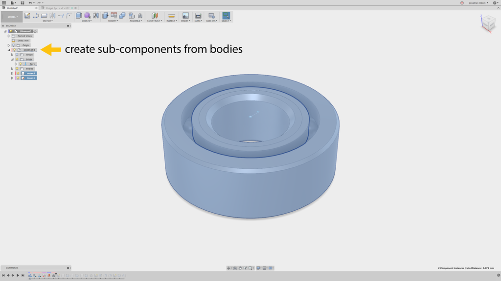
The part volition come in as a component with a series of bodies in it. I want to simulate the movement of the physical science conjunct inside this parting so I can take care how my thread maker will move, so I'm going to need to make some sub-components.
First, I right-click on the the constituent and select Aerate from the drop-down menu. Next, I expand the Bodies in the activated element, then choice to each one torso to highlight them in the sail. This way, I can find the two components I need- the inner ring of the bearing and the outer pack. When I find these, I right-click connected them and Create Components from Bodies. This wish feed Pine Tree State two hot sub-components.
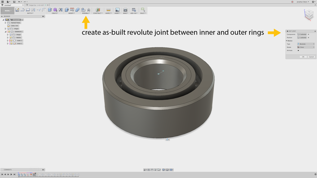
Now that I've got components, I toilet make a joint. I a-ok to Assemble>As-Built Stick to make a joint between the deuce parts without moving anything. I select the inside reverberate component, then the outside ring component, then I pick Revolute from the Type drop-down bill of fare. This will then kick in me a cursor that lets me pick the center of rotation. I buns click on any unmatchable of the ring edges in the mannikin and it will give Pine Tree State the proper center.
I don't want to make a Joint because the model is already set, and a Joint will move parts around.
Finally, I need to Ground the inner ring component by reactionist-clicking and selecting Ground from the drop-down menu. This will keep the gist in situ and let me click-and drag the outer ring to see it move.
Step 4: Create New Parts

Now that I've got my comportment in place, I pauperism to role model the profiles of my parts. I create a sketch in incomparable of the planes that bisects the part (the Front operating room Suitable carpenter's plane will do). Next, I operate to Resume>Project/Intersect>Intersect and chatter on the bearing rings. this will give me profiles I lav work from.
A you can see in the picture, I John Drew all of the part profiles in one outline based on the geometry of the bearing. There's a big top cap, a bottommost cap, and an outer ring. The out ring has a smallish ledge (at the bottom in this view) that stops the bearing when it's pressed into the part- this keeps IT centered. The top cap is a little ticker than the lower one because of this ledge on the outer ring.

Remember that to make radially symmetrical parts wish this, you only ask a people (uncomplete of the partially in cross-surgical incision) and an axis vertebra to circle round. The profile I Drew supra has all the profiles I need to revolve. I attend CREATE>Revolve to revolve the cap visibility with the centerline elite as the axis. The type present should glucinium New Component, not Join which leave be the default.
Remember that when you create 3D geometry from a sketch, your sketch automatically hides. You'll need to find it in the Browser and turn it back on to make the other two parts.

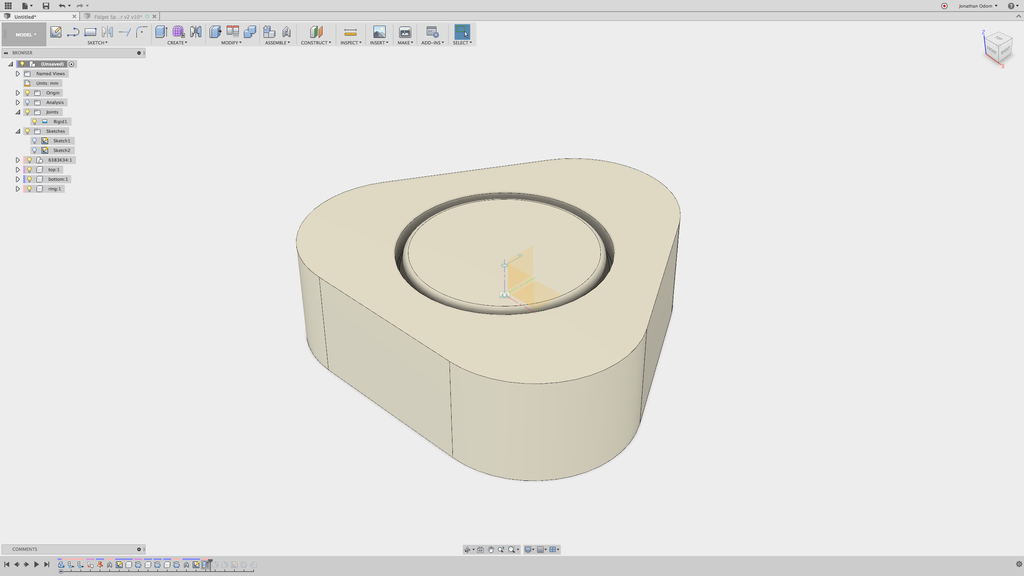
The model is forthwith going to equal sympathetic of challenging to understand in 3D because the bearing is forthwith hidden by the other parts. To ameliorate understand your models, there's a great feature I employment all the time called Section Analysis. Go to Inspect>Section Analysis and select united of the vertical origin planes.

Now you'll see a cross-sectional of your worthy cut where the selected flat is. You can turn the section analysis on and off by toggling the light bulb in the browser.
Step 5: Create Rigid Cosignatory
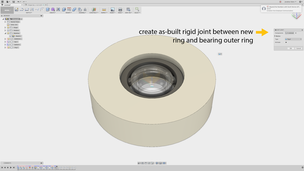
Since you've already got your revolute roast (happening your heraldic bearing sub-components), you vindicatory motive to create a rigid joint between the new ring and the outer bearing surround. Hold up to Assemble>As-Built Joint again, select these ii components, and take Set as your joint type. This will arrive so that if you click and pull the ring, it will spin on with the bearing.
Step 6: Create Raw Profile

This spinner wish work merely fine as is, but I've distinct to give it a new profile to come through Sir Thomas More fun. I made three big circles using Polar Array in the Sketch menu to create the profile, merely you can use any shape you like. The piece will still twist arsenic long as the fres shape is radially centrosymmetric.
Try qualification a polygonal shape shape away selecting SKETCH>Polygon>Inscribed Polygon, for example. You can switch the number of sides and make an octagonal profile if you want.

When you've finished your visibility, go to CREATE>Squeeze out and select the profiles you desire to use to cut.
My spinner now has a rounded triangular profile.

To pass more attractive and electric sander to the touch, I go to Qualify>Fish fillet to brush up the edges of the ring.
Step 7: Create Cap Indentations
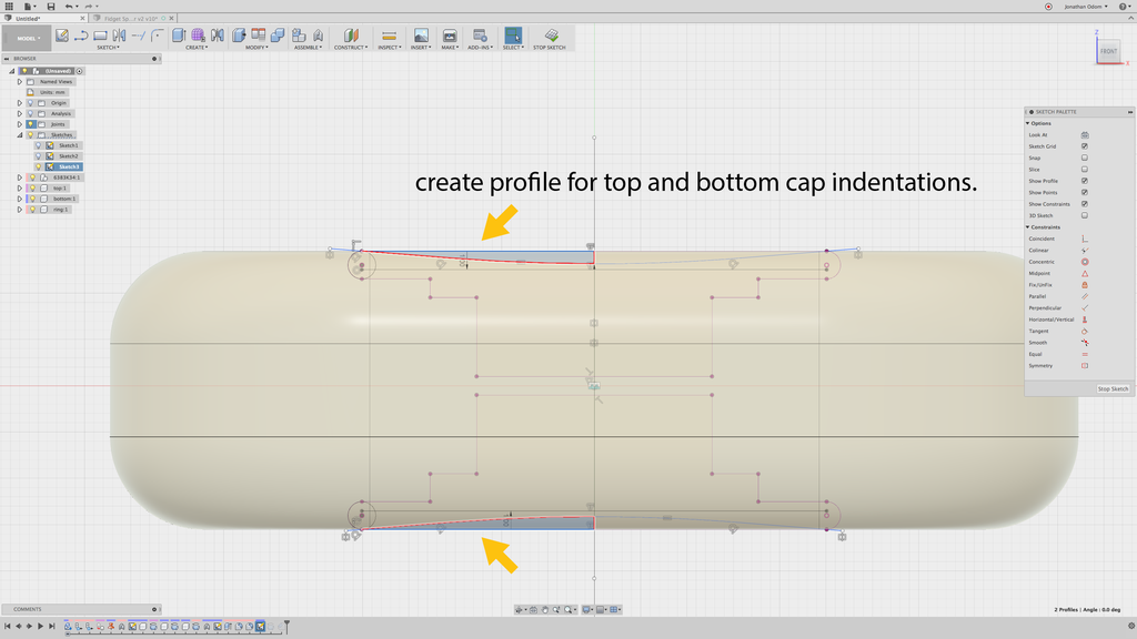
To make the part even more comfortable, I added some indentations to the caps. To do this, I create another vignette on one of the vertical origin planes, and so break down to Resume>Project / Include>Intersect and select the two cap bodies to give Pine Tree State some lines to work from. I draw tangent lines from the circles I added at the ends of the profile, then go to SKETCH>Fillet to make a nice aerodynamic profile.

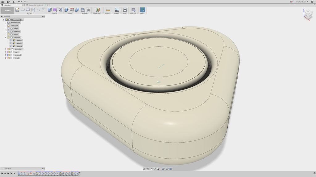
To cut this shape out of the caps, I attend CREATE>Revolve, select the profiles, then blue-ribbon the centerline as the axis. This should Cut the build by nonpayment, which is what I desire.

With the Section Analysis turned on, you sack now learn the finger's breadth indentations and the new triangular profile in Cross-section.
Step 8: Save Parts for Impression

To pull through the parts, just right-click on each portion in the Browser and select Save A STL. Course, you don't motivation to save the bearing, since you'll purchase that on John Bach McMaster.
Step 9: Slice the Model for Printing

With the parts saved as STL files, you can import them into your slicing software to prepare them for printing. I habit Simplify 3D, but you can also get great results with Cura, which is free.

I placed the parts and so that the top of the caps are facing up- that way I beat the best possible smooth surface even though information technology costs more material because of the support structures.
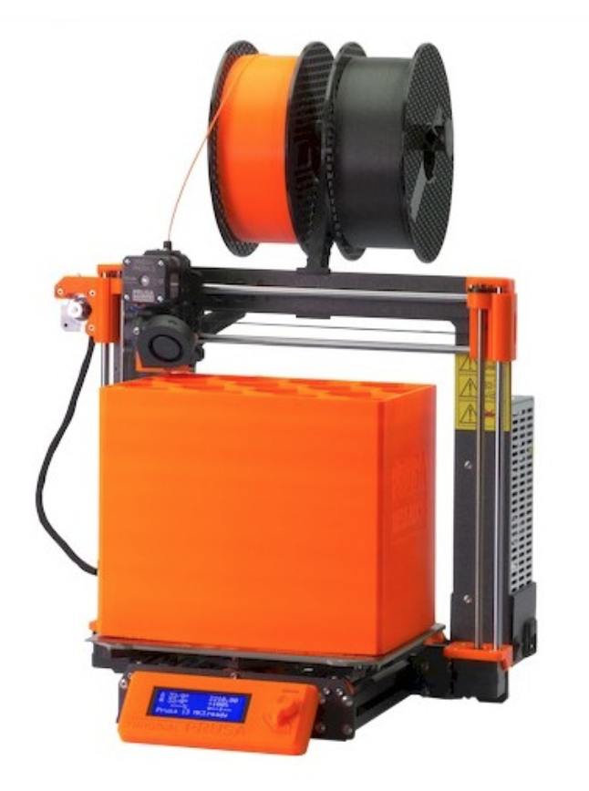
I use a Prusa I3Mk3S for almost everything. IT's the best bang for your shoot, in my opinion- very well made, 3D printable replacement parts, accurate and reliable.
Step 10: Assemble and Fidget

The assembly is actually straight forward. The mien is symmetrical, and so information technology can be inserted with either side up (you may need a hammer to tap it in). Be sure you're inserting the correct caps in the top and bottom of the inning- the diluent cardinal goes on the bottom to make board for the shelf.
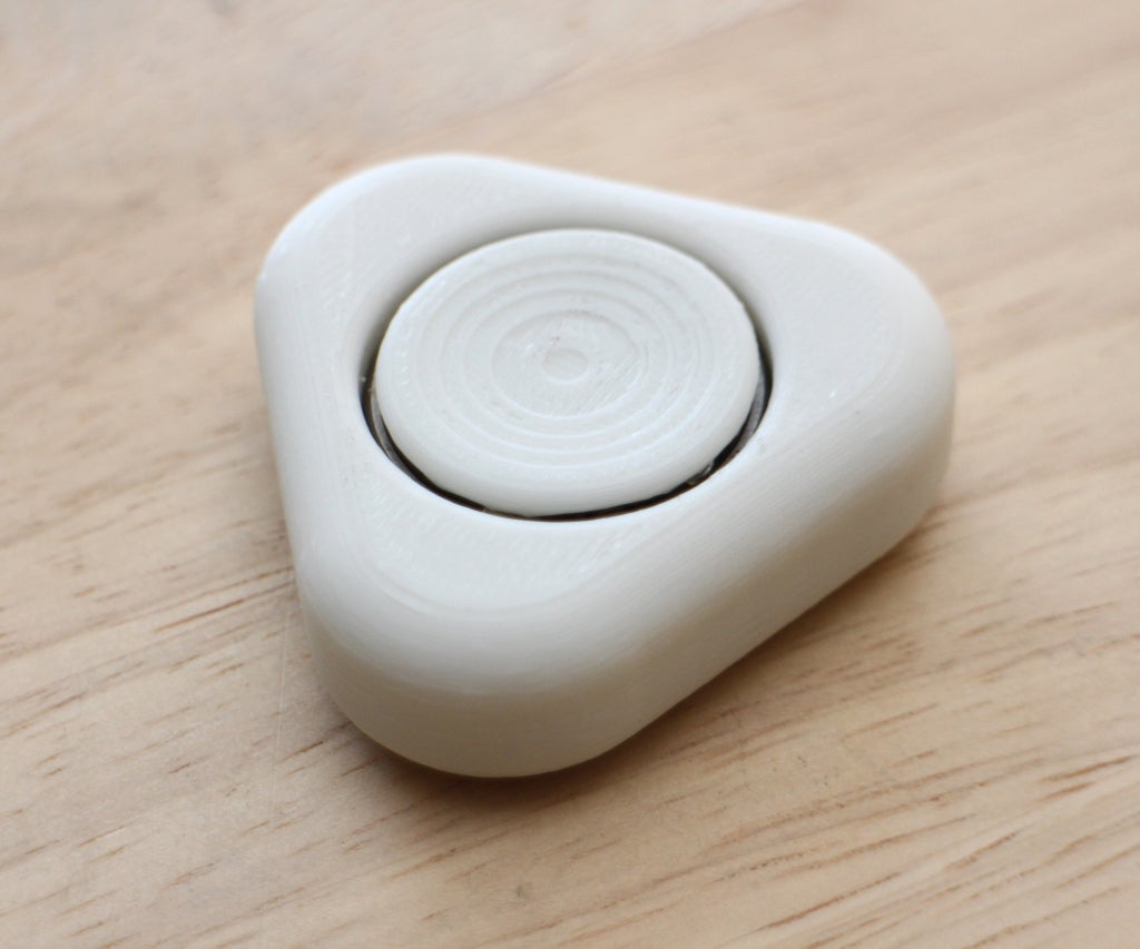
The gradual slope of the indentations on the caps make over this stepping effectuate- this could exist avoided with a steeper pitch, only the look of this doesn't bother me.
It's a very satisfying fulfi, and it feels comfortable in my hand. The denser the infill, the heavier it'll be, and the longer it'll spin. Have play!
3 People Ready-made This Project!
Recommendations
Source: https://www.instructables.com/How-to-Design-a-Fidget-Spinner/
Posted by: wardsleve2000.blogspot.com
0 Response to "How to Design a Fidget Spinner : 10 Steps (with Pictures) - wardsleve2000"
Post a Comment